| |
With all the work that had to be done on the KS601, why ever would I choose the tail light as a
starting point?
I didn't know the etiquette of a road run at a rally, but I knew that a lot of the folks there,
while truly loving their machines, were not highly polished riders. With the bunch I ride with,
no brake light would be a point of concern, but not a show stopper. With less experienced people
in a large group, and me being unfamiliar with the Zundapp to boot, I felt no brake light really
meant no ride, even in the unlikely event their rules didn't stipulate that. So that's why it
was first.
|
|
|
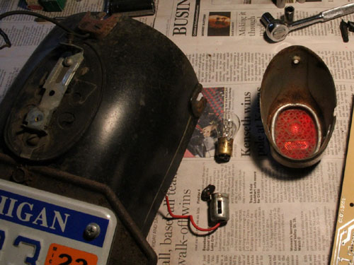
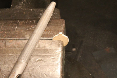
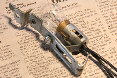
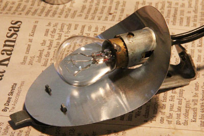
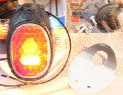
Here you see the tail light almost as found. The only thing you missed is how the socket
was artfully strapped to the mount by electrical tape.
Zundapp KS601's did not have a brake light from the factory, only a single filament tail
light with a single contact socket to match. So it appears some previous owner decided
to remedy this shortcoming and removed the original socket, replacing it with this one
which is correct for a dual filament bulb. That, apparently, is where that project came
to a rest, after the socket was taped to the mount.
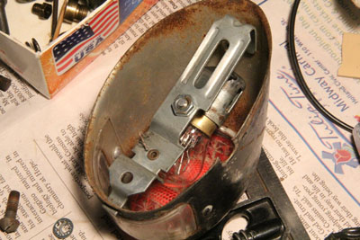
Another issue, in my view, is no reflector. I don't see any provisions for one, so I am
assuming there never was one. Six volt lighting is marginal at best, and for a six volt
brake light to be effective it really seemed important to me that as much of the meager
light as possible be directed toward the idiot behind me, not bouncing around inside the
tail light housing.
|
|
|
The Zundapp KS601 tail light as found. Note no reflector.
|
|
|
The Process
|
|

|
|
|
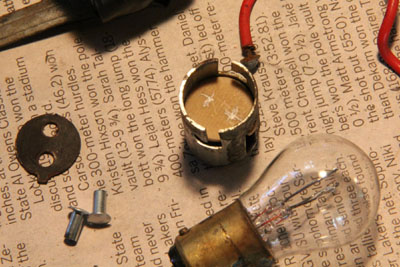
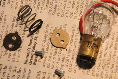
The socket, borrowed from some other light assembly, had one
tab missing from the insulator. The contact had nothing to
hold it in place or insulate it from the spring.
The bulb is an 1154 six volt dual filament. These have the same
base as an 1157 but are typically only a bit north of 5 watts
for the tail light filament and 16 watts for the brake light.
In comparison, a standard 12 volt 1157 puts out around 8 watts
for the tail light and a substantially higher 27 watts for the
brake.
Another potential candidate, although a bit harder to come
across, is a 7517 which puts out 5 watts running and 21 watts
braking, quite a bit closer to the 1157.
|
|
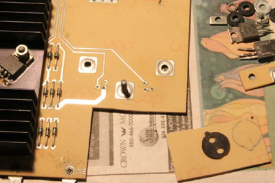
I generally have a few circuit boards lying around waiting to get
the components stripped off them for reuse. I think in the
future I'm going to make sure I keep a few for projects such
as this one.
This board is really nice dense material and perfect to make
the replacement insulator out of. Usually circuit boards this
color are cheaper material, but this one was pretty high
quality stuff.
I thought it would be tricky to drill the holes for the contacts
without chipping out the board. Planned on using a high speed
drill, but the stuff cut and shaped so nice I just used my
2500 RPM 1/4" Milwaukee.
|
|
|
|
|
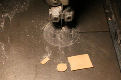
The new insulator cut out of the donor circuit board.
|
|
Getting the shape just right.
|
|
|
|
Here's the insulator all nicely shaped and fitting just perfect in the
socket. Now, I need to drill those holes.
The missing tab is evident on the original insulator.
|
|
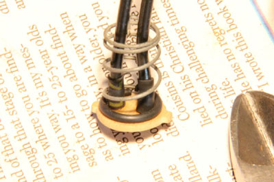
The finished insulator with holes drilled. Note the tin plated
brass rivets to be used as contacts. They have an ID drilled
most of their length to pocket the wires into for soldering.
The spring has the end covered with high quality heat shrink
tubing to insulate the bottom from the wires.
|

|
|
|
Contacts in place and wires soldered.
|
|
Insulator assembled and ready to go in the socket.
|

|
|
|
Mounting tab welded to socket. I'm afraid my TIG skills were getting
a bit rusty at that point. They've since made a substantial recovery,
not quite to that of the days of old, but getting there.
|
|
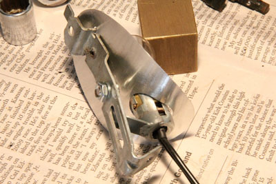
Here's the finished socket and mount assembly with just a puff of paint
on the socket bracket to keep it from rusting. Note the filaments
are oriented for max light to strike the lens.
|
|
|
|
A trial fit of socket and mount assembly to verify the bulb and
filaments are in the best position to get max light out the
lens.
|
|
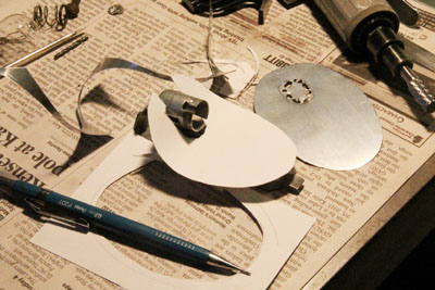
Ok, time to make the reflector. Easier to start with a chunk of
poster board to get the initial size and shape, then duplicate
in a piece of aluminum flashing.
|
|
|
|
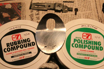
Here's the finished reflector after a bit of effort,
shaped to click onto the socket and mount and polished
to a nice shiny surface.
|
|
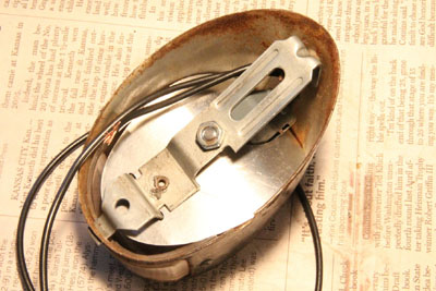
The reflector clipped onto the socket and mount, no
fasteners required. The flashing is quite springy, so
it's very firmly attached with no fear of it vibrating
off in use.
|
|
|
|
Another look at the reflector from the back. Fits rather nicely,
if I may say so.
|
|
A view of the finished assembly tucked into the KS601's
tail light housing. Maybe could have extended the reflector
a tad more toward the bottom, but it looks pretty good all
in all.
|
|
|
The Zundapp KS601 has a removable rear fender to facilitate pulling the rear wheel off. You
get some impression of that in the image at the top of this page. If you squint you can see,
just above the tail light mount, a brown phenolic contact block. This acts as a connector for
the tail light, mating with another similar half on the larger chunk of fender that remains on
the bike.
The problem is that it is a single contact. I've considered layering another above it to carry
the brake light connection, or making a thinner two contact version out of phenolic. Either idea
would look a bit bulky. Also, I have decided I want a dedicated ground to the tail light socket,
so either of these ideas would be pretty impractical looks wise. I think I will probably just
run the tail light wire through the original connector, then do as neat a job as I can of
running the brake light and ground wires parallel to it, with their own connectors to allow
removal of the fender. We'll see...
|
|
The Results
|
|
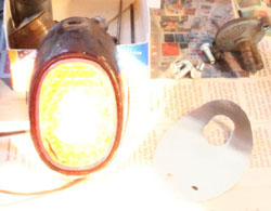
Well. After all that it's time to see how it works, particularly if the time used
making the reflector was well spent. The four comparison pictures to the right, below,
were all taken with the camera and the power supply at exactly the same settings to
facilitate determining relative brightness, so forgive the over exposures. I was
intentionally metering off the lens and ignoring everything else.
|
|
|
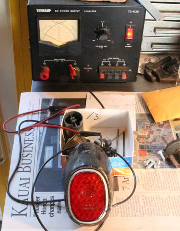
The test set up, with my Tenma 1-15V, 30 amp power supply.
Very useful for automotive and motorcycle stuff.
|
|
|
|
|

|
Tail light alone, no reflector.
|
|
Tail light alone,
with reflector.
|
|
|
|
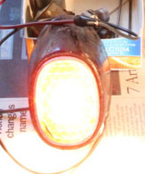
Brake light alone, no reflector.
|
|
Brake light alone,
with reflector.
|
|
|
|
I have to say it was well worth it. The running light is marginally improved, but the brake
light is distinctly brighter. I tried to keep the camera angle similar to the angle a driver
following the bike would be viewing the tail light from. Note that it was actually a little
higher on the picture of the brake light with the reflector installed, so I think it's really
a bit brighter than it looks here, relative to the no-reflector image.
Conclusion - definite improvement.
The astute will notice the meter is indicating 5 volts. Got this power supply for $10 from a
garage sale. The meter was pretty beat up and the fan was stuck, so I took the supply apart,
lubed the fan, freed and straightened the meter's needles, and replaced the bezel. The meter
is slightly non linear, but no means to linearize it other than adding some electronics, so
I say good enuf. I set it to be close to nominal at 10 volts, increasingly offset negative
below that, and positive above. When the dial says 13.6, the output is right there, so I've
got that for a reference. Just need to put a sticker on it. It regulates right on the money,
pure clean DC with 30 amps behind it if you need it, and the current indicates accurately.
|